01 / EPC1
EPC
Project configuration support based on electrical and site requirements.
PROJECT-BASED
C&I ENERGY STORAGE
A C&I energy storage system stores electricity for commercial and industrial site applications. LinkPower configures battery, PCS matching and system integration around the application, load, power, energy, runtime and site conditions.
WHO IT IS FOR
C&I storage for EPCs, project contractors, system integrators and commercial project developers.
Project configuration support based on electrical and site requirements.
Configuration review for installation scope, voltage and site conditions.
Battery system, controls, communication and site integration coordination.
Project planning around load profile, application, timing and site conditions.
START WITH PROJECT DATA
Start with the application, operating and peak load, required power, target energy capacity or backup duration, AC voltage and phase, existing PV or generator, grid condition, installation environment, country and project timeline.
Application objective, load profile and required backup duration. Common objectives include peak shaving, demand management, PV self-consumption, backup power, time-of-use shifting and weak-grid or microgrid support.
Confirm required power and energy, AC voltage and phase, and any existing or planned PV system, generator or grid connection before configuration.
Confirm site conditions, grid or weak-grid context, installation environment and project timeline.
PROJECT-CONFIGURED C&I
Project-configured C&I is the primary route. Start with the application, load profile, power, energy, backup time, AC voltage, phase, PV, generator, grid and site conditions.
Define the application, load profile and required backup time. Confirm the operating objective, such as peak shaving, PV self-consumption, backup power, time-of-use shifting or weak-grid / microgrid support.
Confirm required power and energy, AC voltage and phase, PV, generator or grid connection, and the required backup time before configuration.
Confirm site conditions, installation environment, grid or weak-grid context, AC voltage and phase, PV or generator integration, and the project timeline.
SYSTEM CONFIGURATION
System scope is defined around the actual application, electrical requirements, site conditions and project documentation needs.
Battery system architecture and thermal management are configured for the project scope.
Control and communication requirements are reviewed with the wider project system.
Site integration, safety requirements and project documentation are reviewed together.
C&I PROJECT FAQ
Answers for EPCs, contractors, system integrators and project developers preparing a C&I energy storage inquiry. Final configuration is confirmed only after project data and site requirements are reviewed.
Send the application, operating and peak load, required power, target energy or backup duration, AC voltage and phase, PV or generator details, grid condition, installation environment, country and project timeline.
kW describes power: the rate of charging or discharging and the load the system needs to support. kWh describes stored energy. Both matter: adequate energy does not guarantee sufficient discharge power, and adequate power does not establish backup duration.
Define the actual critical load and how long it must remain powered. Energy capacity, available discharge power, conversion losses, operating limits and the selected configuration are then reviewed. A nominal kWh value alone does not guarantee the required runtime.
Integration can be reviewed, but is not automatic. Send PV and generator ratings, existing inverter or controls, the grid connection and the intended operating modes. PCS matching, controls, protection and source coordination are confirmed for the project.
Provide country, installation environment, available space, access constraints, AC voltage and phase, grid condition, existing PV or generator and project timeline. Include a site layout or single-line diagram when available so the integration scope can be reviewed.
PROJECT INQUIRY
Share the application, load profile, required power and energy, backup time, AC voltage and phase, PV, generator, grid context, site conditions and project timeline for configuration review.
C&I PROJECT REQUIREMENTS
Provide the technical and site information available for your project.
SYSTEM ARCHITECTURE
A clean view of the configurable energy path from PV, grid and generator inputs through PCS, the LiFePO4 battery system, BMS / EMS / controls and the site load.
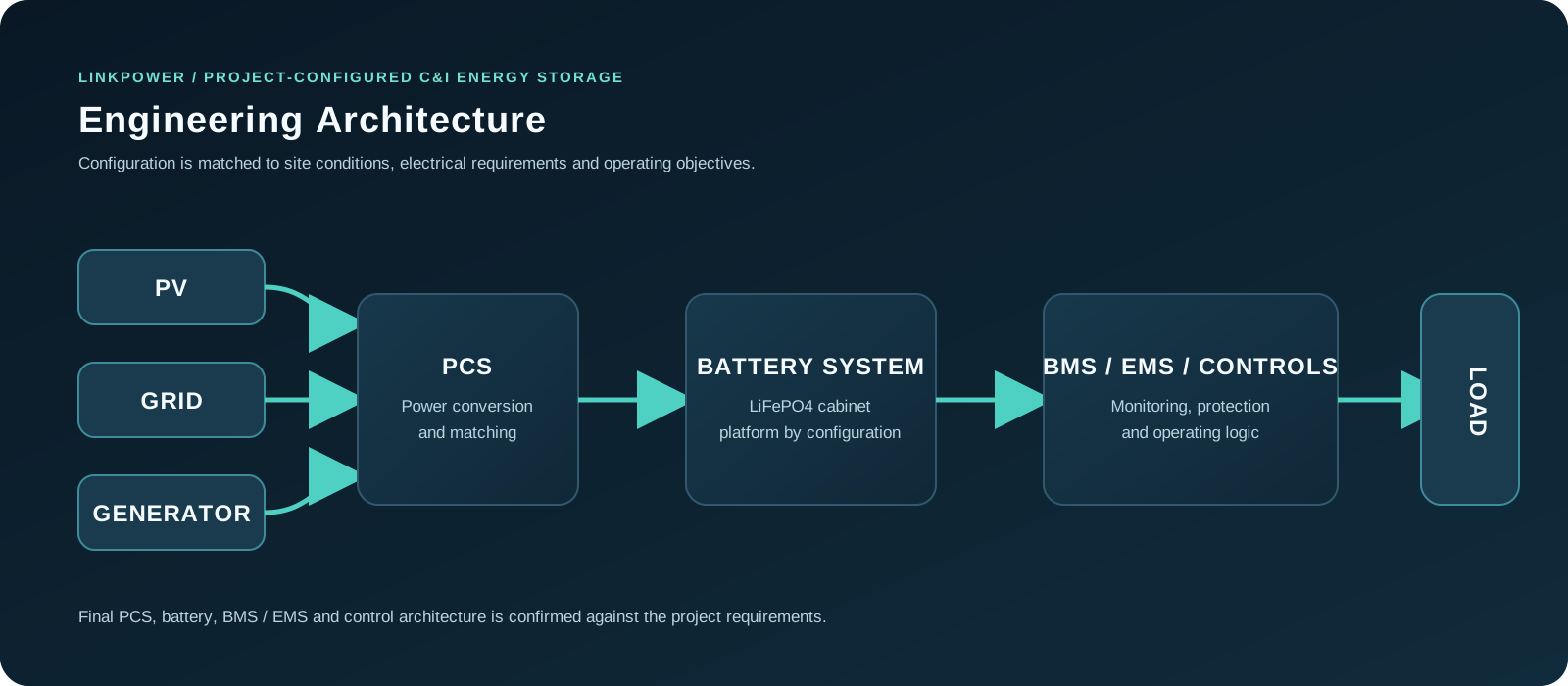
PV, grid and generator inputs connect through PCS to the configured battery system and site load. Open the image for a full-size diagram. Final topology is confirmed for the project.
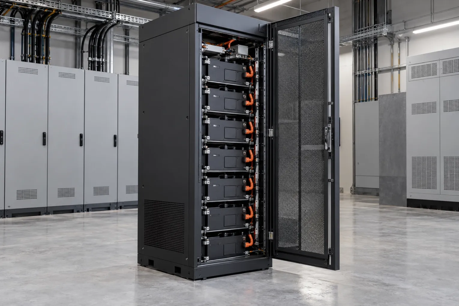
PCS and the LiFePO4 battery platform are selected around power, energy, voltage and backup requirements.
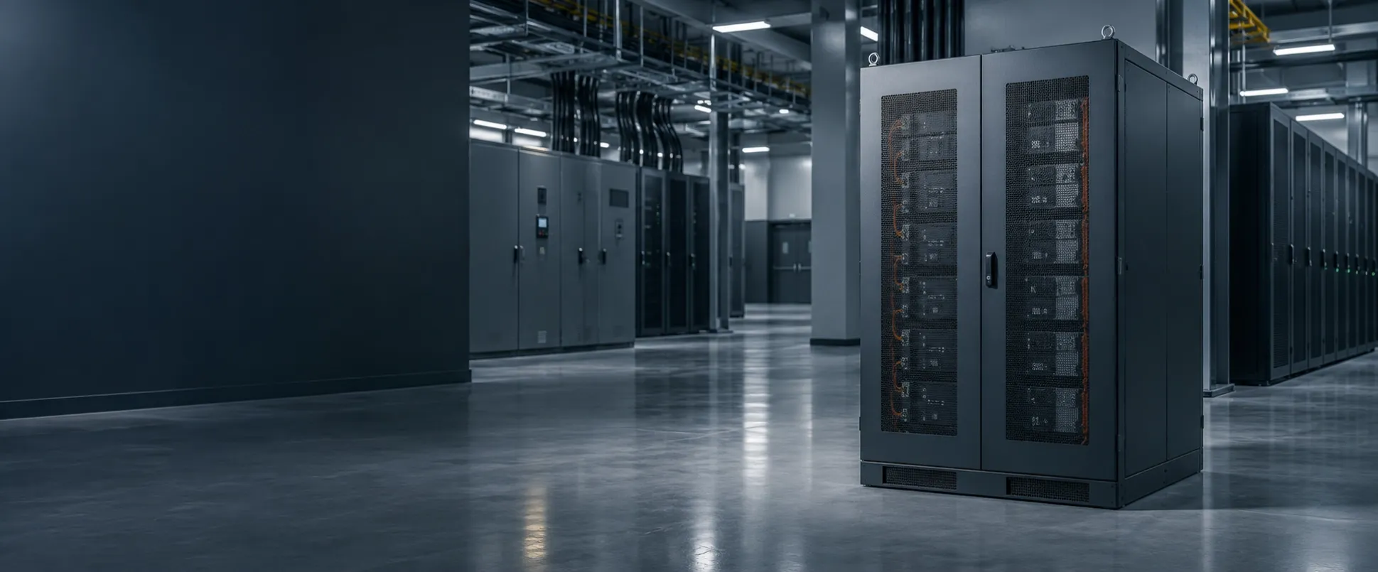
BMS / EMS / controls coordinate monitoring, protection and operating logic for the project.
SYSTEM CAPABILITY
System scope is matched to the application, electrical requirements and site conditions. Final equipment, controls and cooling approach are confirmed by project configuration.
LiFePO4 battery cabinet and high-voltage platform options are reviewed according to required power, energy, voltage and installation environment.
PCS is selected and matched according to project requirements. BMS, EMS, protection and controls follow the selected project architecture.
Air or liquid cooling, RS485 / Ethernet options and other communication interfaces depend on the selected system. Confirm the final configuration before quotation.